
Fig. 3. Free-space optical mode matching.
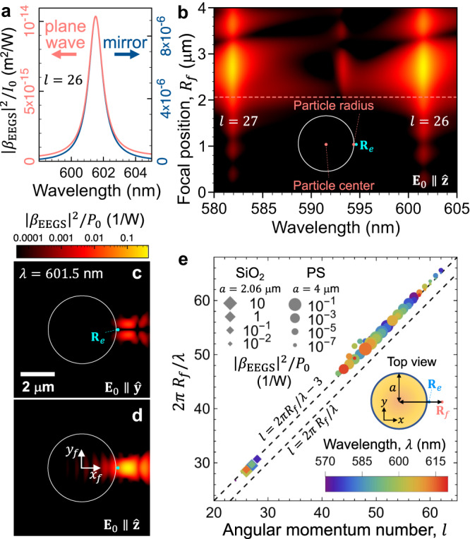
Dependence of the EEGS probability on the illumination conditions for a SiO2 sphere of 4122 nm diameter. a EEGS probability around a 601.5 nm resonance for plane-wave and mirror-focused illumination, normalized to the light intensity incident on the sphere and mirror, respectively. b Dependence of the EEGS probability on light wavelength and focal spot position. The vertical axis corresponds to the distance from the focal spot to the sphere center as it moves along the x (horizontal) axis (see inset). c, d EEGS probability maps at the peak wavelength of (a) with Rf = (xf, yf) scanned for incident light polarized along y and z, respectively. The sphere contour is shown as a white circle. The color scale is shared by panels (b) to (d). e Optimum optical-focus position Rf as a function of orbital momentum number l for resonances in PS (circles) and SiO2 (diamonds) spheres of diameters 8000 and 4122 nm, respectively. Symbols show all modes of high quality factor within the λ = 570−620 nm spectral region (see color-coordinated scale). The EEGS probability is indicated by the symbol size (see legend). The dashed straight lines correspond to 2πRf/λ equal to l and l + 3. In (a), (b), and (e), the e-beam passes at a fixed position ~80 nm away from the sphere surface on the x axis, as indicated in the insets. The intensity I0 and power P0 of the light incident on the mirror are related through P0 = A I0, where A = 18.74 mm2 is the mirror area.