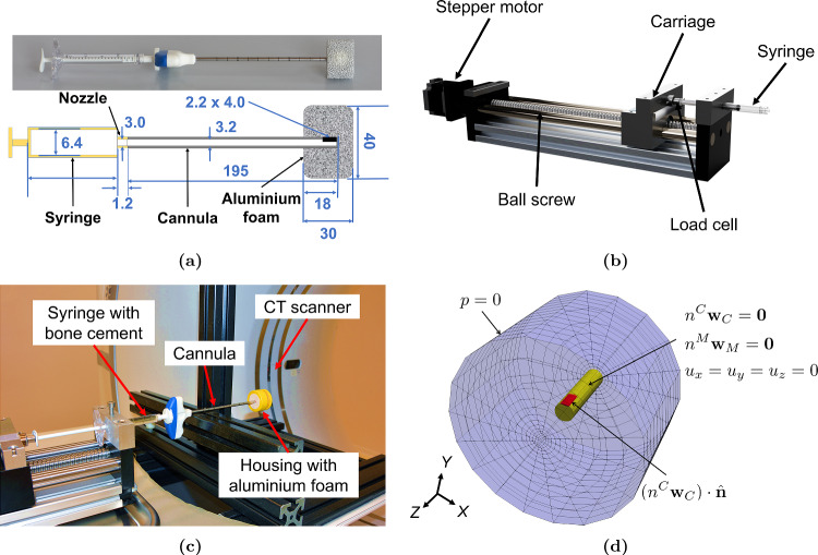
Fig. 2.
(a) Bone cement injected into aluminium foam (above) and its schematic with dimensions in mm (below). The figure is not to scale. (b) Custom-made bone cement injector used for flow-controlled injection (c) Setup for the benchmark experiment (d) Geometry and boundary conditions for numerical implementation of injection inside the aluminium foam, where the cannula walls (yellow) were assigned no-slip and clamped boundary conditions, while the outer walls (blue) of the foam were assigned zero pressure. The opening for the inflow (red) was assigned velocity by dividing the flow rate by the area of the opening

