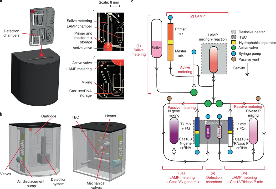
Fig. 6 |. Design of an automated microfluidic-driven diagnostic system.
a, Left: illustration of the final instrument in which the cartridge is inserted. Inset shows picture of the entire microfluidic gravity-driven cartridge. Right: images of the sample metering and rLAMP reaction chamber (1), rLAMP metering and Cas13 mixing chamber (2) and the detection chamber (3). b, Front (left) and rear (right) illustration of the instrument components, including detection system, heaters, air-driven valves and mechanical valves. c, Schematic of the cartridge function. The reaction can be separated in four steps: saliva metering (1), amplification reaction (2), post-amplification metering + Cas13 mix (3), and Cas13 reaction in detection chambers (4). Reagents stored on the cartridge are separated via a proprietary hydrophobic solution to avoid premature initiation of the reactions. After the LAMP reaction, the sample can be split into two reactions: the left part of the cartridge will expose the sample to N gene crRNA (step 3a), while the right side of the cartridge will act as internal control with only RNase P crRNA (step 3b). Saliva samples went through only step 3a, while clinical samples went through steps 3a and 3b.

