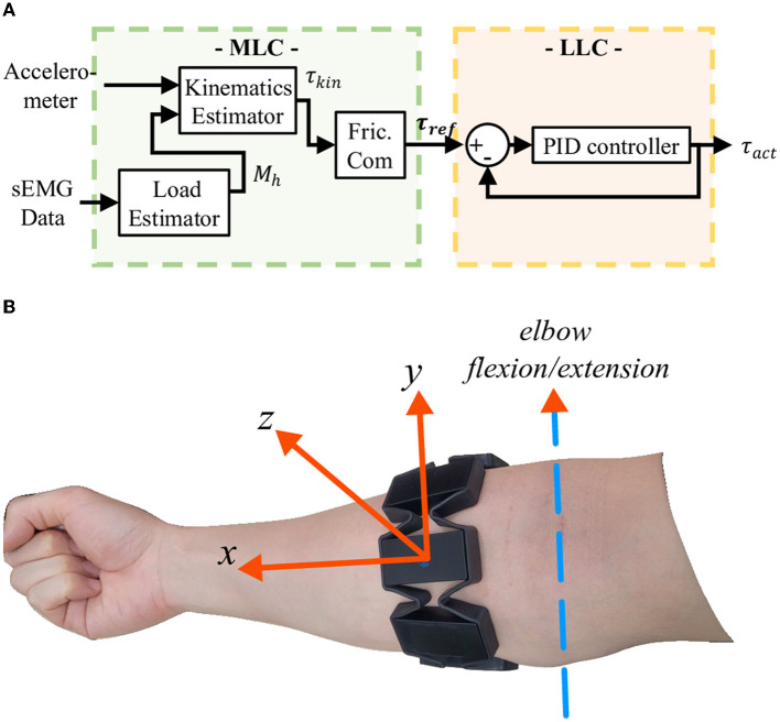
Figure 4.
(A) Controller block diagram. The MLC consists of three control units as follows: arm kinematics estimator, load estimator, and friction compensator (Fric.Com). The two estimators estimate the required assistive torque based on arm kinematics and an external load being carried in the hand. The friction compensator amplifies the kinematic torque τkin to compensate for the friction on the Bowden Cable. (B) Alignment of the accelerometer integrated within the MYO.

