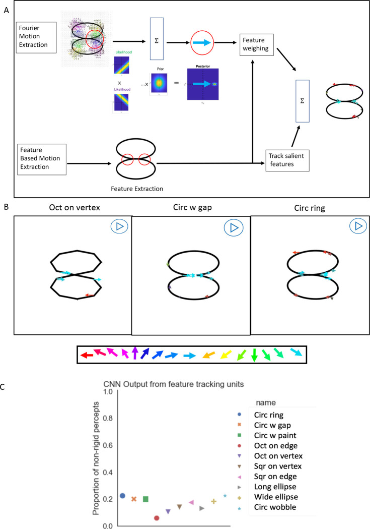
Figure 7. Feature tracking mechanism.
(A): Two feature tracking streams simulating MT pattern-direction-selective (top) and feature-extraction based motion (bottom). Top: the inputs are the vectors attained from the motion energy units and each motion energy vector creates a likelihood function that is perpendicular to the vector. Likelihood functions are combined with the slowest motion prior by Bayes’ rule. The output vector at each location is selected by the maximum posteriori. Bottom: salient features (corners) are extracted, and a velocity of the feature is computed by picking up the highest correlated location in the succeeding image. The outputs from two streams are combined. (B): The preferred velocity of the most responsive unit at each location is shown by a colored vector using the same key as Figure 6. Stimulus name is indicated on the bottom of each section. Most of the motion vectors point right or left, corresponding to the direction of rotation. (C): Average CNN output based on the feature tracking vector fields being the inputs for different stimulus shapes, shows higher probability of rigid percepts.

