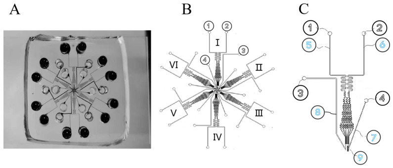
Figure 1.
Schematic diagram of microfluidic chip structure. (A) Physical diagram of microfluidic chip. (B) Schematic diagram of 6-channel chip. The numbers I- VI represent that this chip is a six-channel chip. Among them, I, II and III channels were the control group, and IV, V and VI channels were the 30 s experimental group. (C) Single-channel loading unit. ① Chemokine injection port. ② Cell culture solution injection port. ③ Waste liquid outlet. ④ Cell injection port. ⑤ Chemokine transport channel. ⑥ Cell culture medium delivery channel. ⑦ Cell transmission channel. ⑧ Waste liquid channel. ⑨ Cell isolation zone.

