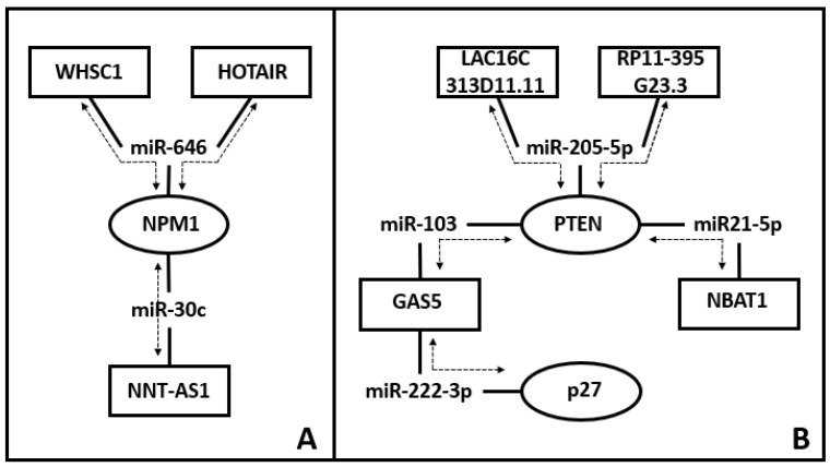
Figure 1.
Examples of ceRNET in EC. The reported examples are only for exemplification purposes, and they are not exhaustive of EC-related ceRNET identified so far. Nodes are ceRNA (i.e., a lncRNA or an mRNA) and in the scheme, they are represented as either ovals (mRNA) or rectangles (lncRNA). Their connections (lines) identify miR interacting with both molecules (one oval, one rectangle). Individual axes (mRNA + miR + lncRNA) are identified by dotted lines with arrows and are the same retrieved by the available bibliography (see below). In panel (A), the two top axes share both a connection (miR-646) and a node (NPM1) and, at the same time, the node NPM1 is shared with the lower axis. In panel (B), a more complex situation is depicted: the two top axes share both a connection (miR-205-5p) and a node (PTEN), which is shared with two additional axes.; o One of these PTEN-linked axes (PTEN/miR103/GAS5) is in turn connected with an additional axis, sharing the node identified by GAS5. Bibliographic sources for these schemes are reported in the references list [70,71,72,73,74,75,76,77].

