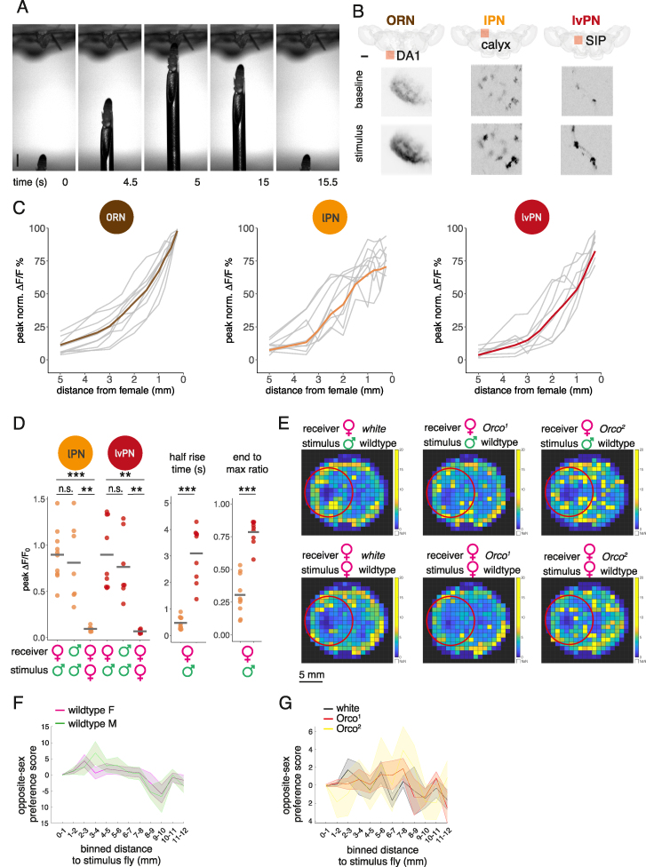
Figure S2.
Parallel cVA pathways signal male distance and sustained presence differently, related to Figure 2
(A) Image sequence from a video of a single male presentation. A fixed female fly is placed in a holder for two-photon imaging (top). A male fly is glued to a needle that is moved by an externally controlled micromanipulator. Note that at timepoints 0 and 15.5 s, the fly has been positioned at the same location with micron precision. Scale bars, 1 mm.
(B) Locations (top row) and example GCaMP fluorescence images (bottom row) of imaging ROIs for ORN, lPN, and lvPN imaging. Fly brains are shown from a top view, which is also the perspective of the imaging objective; orange squares show the location of the ROIs; (ORN, DA1 glomerulus; lPN, calyx; lvPN, SIP). The representative images are averages of frames corresponding to 1 s, before (baseline) and immediately after (stimulus) a male fly was presented at 0.75 mm distance as shown in (A) (also described in Figure 2G). Pixel gray level shows GCaMP signal intensity. Scale bars, 40 μm.
(C) Distance response curves to a male fly stimulus for individual flies in ORN, lPN, and lvPN, based on Figures 2A–2C. y axis: peak values of normalized ΔF/F traces at the ten distances from all measured flies. n = 10, 9, and 8 for ORN, lPN, and lvPN, respectively; 3 trials per fly per distance.
(D) Quantification of responses in Figures 2H and 2I. Left: mean peak responses from individual flies (points), and average peak response (horizontal bar). The sex of the imaged and the stimulus fly is indicated under the x axis. lPN data is in orange, lvPN in red. Middle: half rise time of the responses in Figures 2H and 2I. Right: the ratio of the maximal response and the response at the end of the 10-s stimulus. Lower value indicates stronger adaptation.
(E) Heatmaps of time spent in each 1-mm2 bin in the arena during 20-min recording of a receiver virgin female with an immobilized stimulus. Red circles show the area 5 mm around the stimulus, used to calculate OSP for Figure 2N. Top line: wild-type male stimulus, bottom line: wild-type female stimulus. Receiver female shown, from the left: white, Orco1, Orco2.
(F) OSP at 1-mm binned distances from stimulus: for both wild-type males and females, OSP was highest in bins within 5 mm distance from stimulus (2–3 mm for females, 3–4 mm for males). Lines represent mean OSP within discrete 1-mm bins. Shaded area is SEM.
(G) OSP at 1-mm binned distances from stimulus: white females had the highest OSP within 2–3 mm distance from stimulus, similar to wild-type females, whereas Orco1 and Orco2 females shifted their OSP to greater distances from a stimulus (highest at 8 mm for both). Lines represent mean OSP within discrete 1-mm bins. Shaded area is SEM.

