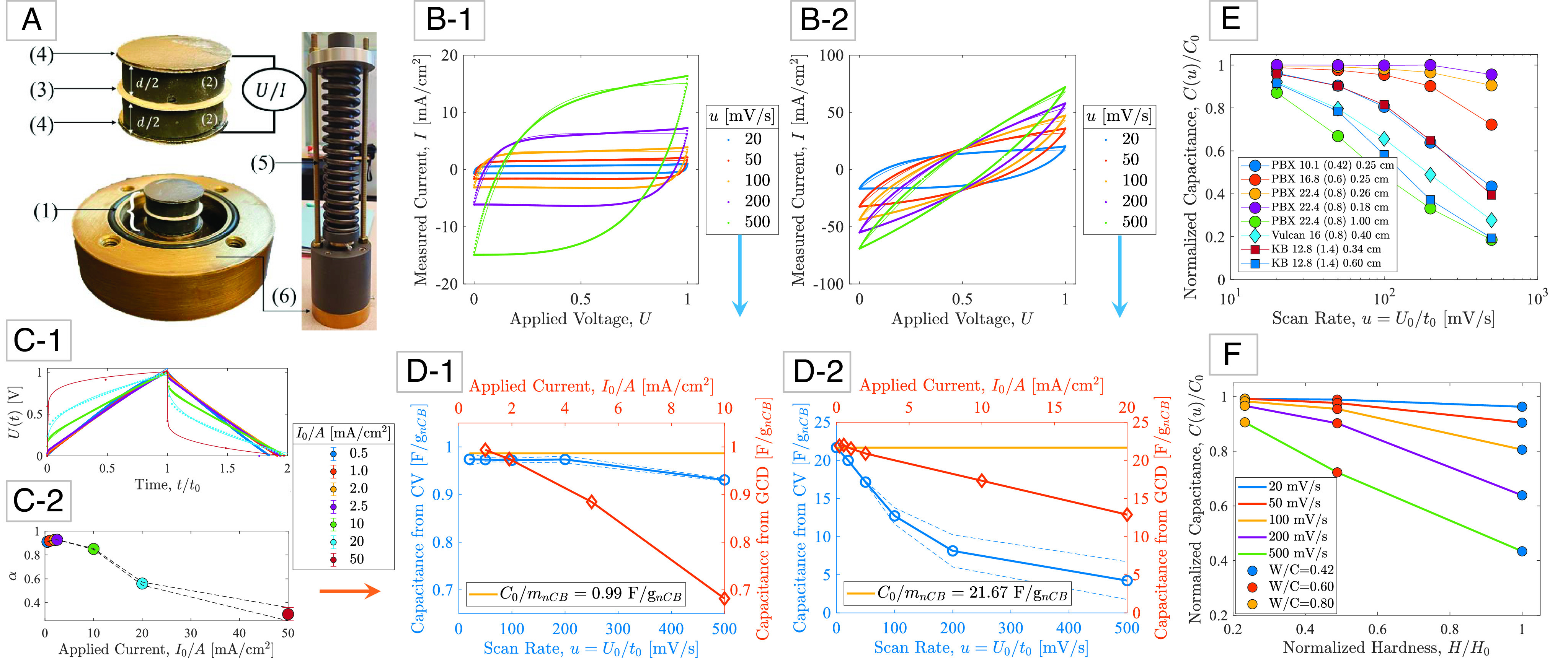
Fig. 2.

Capacitance measurements and analysis: (A) (1) An electric double layer capacitor (EDLC) composed of (2) two polished, electrolyte saturated carbon-cement electrodes (thickness d) separated by (3) a glassy fiber membrane soaked in the same electrolyte (1M KCl), and covered by (4) conductive graphite paper. The electrodes are (5) prestressed in (6) a closed cell to improve contact between the charge collectors and the electrodes (31). (B-1/B-2) Steady-state cyclic voltammetry (CV) measurements of current, I, during cyclic charge/discharge at different scan rates, u = U0/t0, for two carbon-cement electrode samples prepared with different carbon blacks, water-to-cement ratios, and electrode thickness: (B-1) PBX 22.4 (0.8) 0.18 cm, and (B-2) Ketjenblack 12.8 (1.4) 0.60 cm (SI Appendix, section SI-1). (C-1) Steady-state galvanostatic charge-discharge (GCD) measurements of voltage U when a constant current I0 is applied and held constant over time t0, and then removed until U = 0. (C-2) Fractional exponent α as a function of applied current in GCD experiments (error bars represent =/− 1 SD for 500 cycles). (D-1/D-2) Convergence of capacitance measurements from CV-tests and GCD-tests toward a rate-independent specific capacitance C0/mnCB, with mnCB the mass of carbon black in the electrode. The dashed lines represent a 95% CI. (E) Applied to eight different carbon-cement electrode materials of different carbon blacks (12–14), mix designs, and electrode thickness, a characteristic scaling of the rate-dependent CV capacitance is obtained, indicative of the high-rate capability of the electrode materials. (F) Hardness vs. capacitance plot demonstrating that high-rate capability can be achieved with high water-to-cement electrode materials, but at the expense of the material strength.
