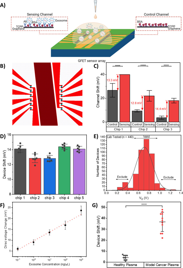
Figure 2.
Design, characterization, and performance assessment of the on-chip integrated GFET device. (A) Schematics of the on-chip integrated GFET biosensor platform with the antibody functionalized channel as the sensing channel and a channel without antibody functionalization as the control channel. (B) Illustration of the layout of on-chip integrated GFET sensor, designed with 6 devices each on the left and right sides. These devices are separated by the central common-on-chip integrated Au electrode. (C) GFET device shift of the control and sensing channels on three GFET chips tested for the same concentration of exosomes in buffer, illustrating the importance of control channel. The GFET device detection signal is calculated based on the difference between the GFET response from control and sensing channels. Error bars are determined by the standard deviation of multiple device measurements, 5 ≤ n ≤ 6 for each reading. (D) GFET device detection signal comparison between the five chips tested for the same concentration of exosomes in buffer, illustrating low device-to-device variation and high chip-to-chip reproducibility of the GFET biosensor. Error bars are determined by the standard deviation of multiple device measurements, 4 ≤ n ≤ 6 for each reading. (E) Device exclusion criteria for GFET reproducibility and validity. Histogram of Dirac voltage for lab-tested GFET devices with Gaussian distribution curve. Device exclusion criteria were set based on 444 lab-tested GFET devices, where the Dirac voltage for lab-tested devices was VD = 0.71 ± 0.24 V. (F) Calibration curve of the GFET biosensor for detection of various concentrations of model cancerous exosomes in buffer. Error bars are determined by the standard deviation of multiple device measurements, 4 ≤ n ≤ 24 for each reading. (G) Measurement results for the GFET biosensor with healthy plasma and model cancer plasma, illustrating excellent selectivity of the GFET biosensor. (****P < 0.0001). Data are mean ± standard deviation (s.d.).

