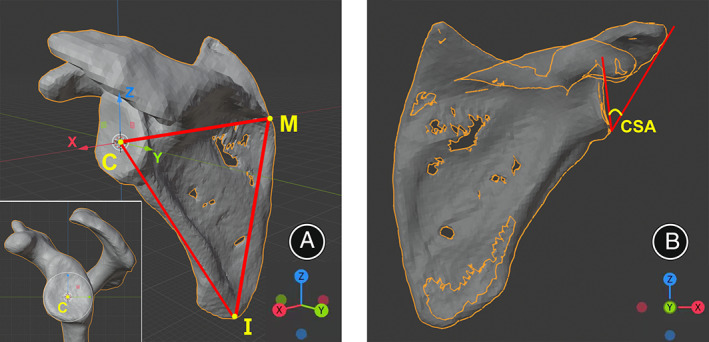
Fig. 1.

Coordinate system establishment on the 3D shoulder model (left shoulder). (A) The scapular plane (I‐C‐M) was identified by three points at the best‐fit circle center of the glenoid (C), the inferior scapular angle (I), and the point where the scapular spine intersects the medial border of the scapula (M). The x‐axis connecting the points M and C, y‐axis normal to the scapular plane, and the z‐axis is defined by the cross product of x‐ and y‐axes. (B) The anterior 3D‐CT view of the scapula was defined as perpendicular to the scapula plane along the y‐axis, and the scapula was toggled to the X‐ray model in this view for CSA measurement.
