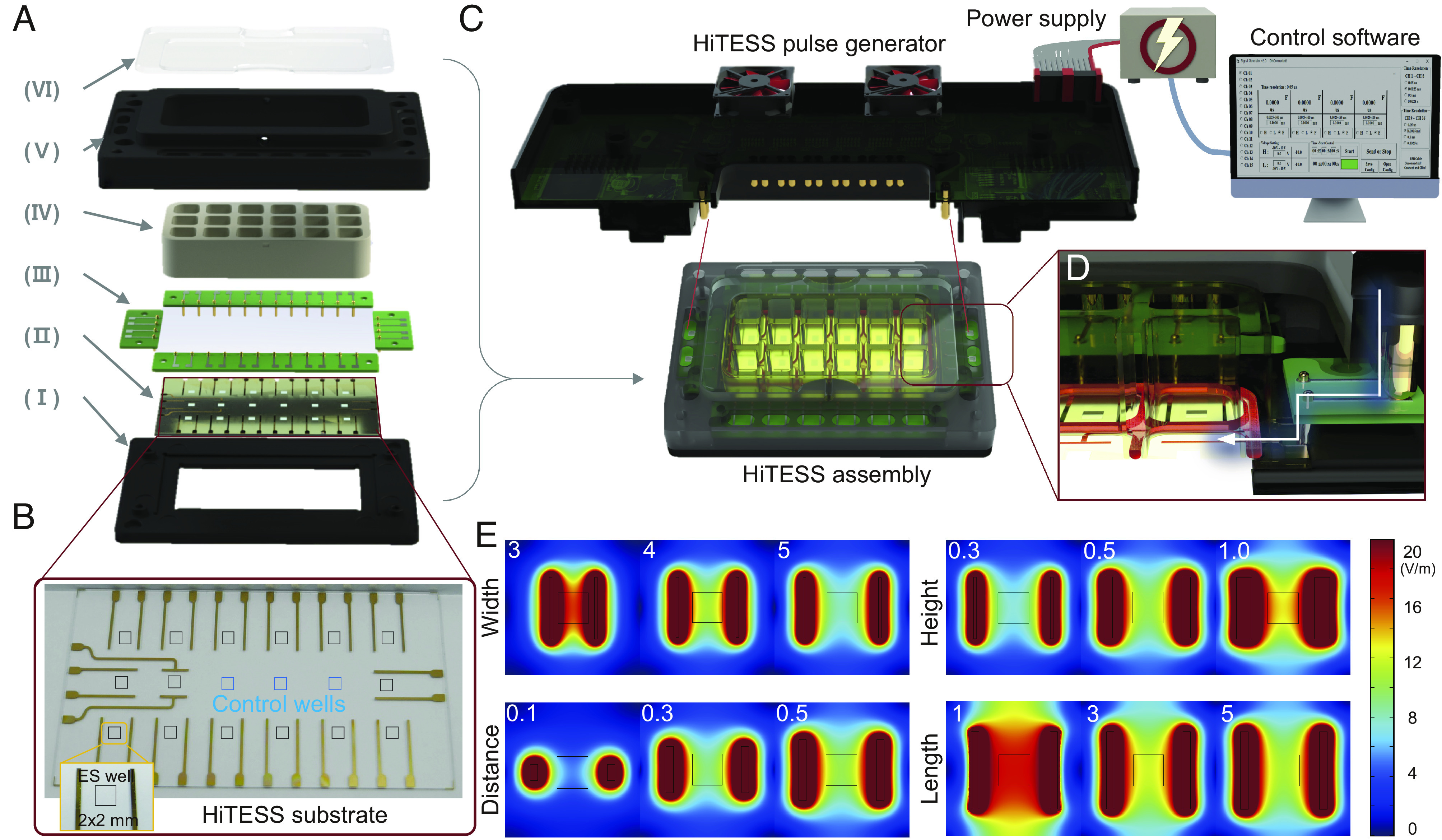
Fig. 2.

Configuration of the HiTESS platform and simulation for electric field optimization. (A) Configuration of the high-throughput electrical stimulation screening (HiTESS) assembly. (I) Bottom holder, (II) HiTESS substrate, (III) connecting PCB, (IV) chamber with O-ring, (V) upper holder, and (VI) cover. (B) Plane view of the HiTESS substrate. The black (ES) and blue (no ES) boxes indicate the individual culture well. (C) HiTESS assembly connected with HiTESS pulse generator. The HiTESS pulse generator was controlled by custom-made control software. (D) HiTESS assembly and HiTESS pulse generator are connected through the contact between the connecting PCB and the pogo pins of the pulse generator. (E) Simulation results of E- fields based on distance, width, length, and medium height.
