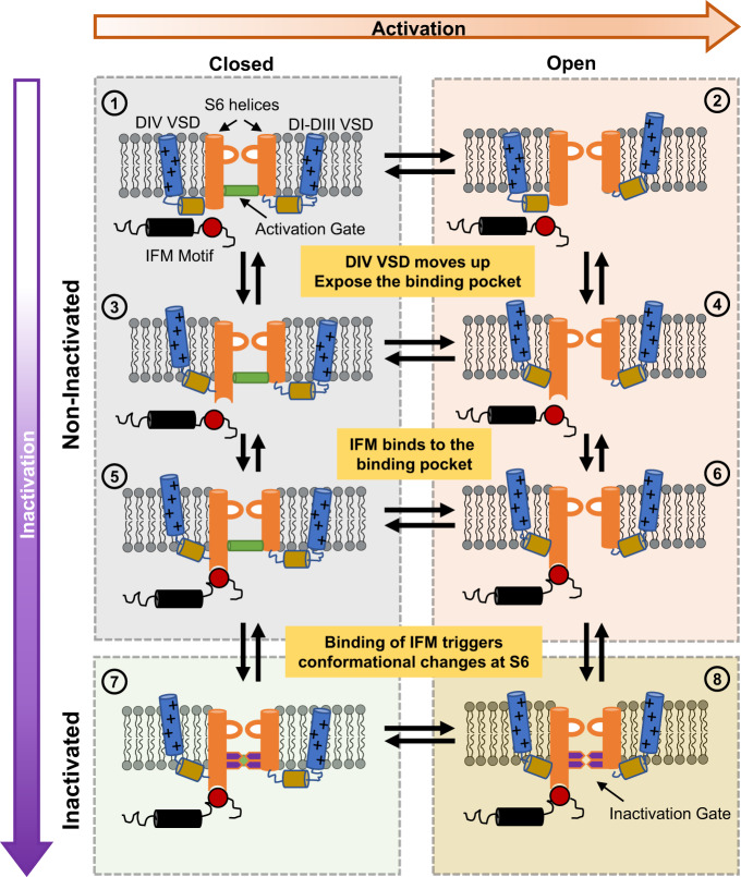
Fig. 8. A general model for fast inactivation from open or closed states.
For simplicity, the multi-step activation is shown as a single transition between the last closed state and the open state in the horizontal direction (rightward), and vertical transitions represent the fast inactivation pathway (downward). ① represents the Nav channel in the last closed state. ② represents the channel with the VSD of DI–DIII in the active (up) position, DIV VSD in the resting (down) position, and a conducting pore: an open channel. Transitions from ① to ③ and ② to ④ occur when DIV VSD moves up, exposing the binding pocket for the IFM motif outside the pore region. Once the binding pocket becomes available, the IFM motif binds and transitions from ③ to ⑤ and ④ to ⑥ occur. The binding of the IFM motif triggers conformational changes that are conducted to the pore region closing the two-layered fast inactivation gate, leading to the closed inactivated state in ⑦ or the open inactivated state in ⑧. Please note that DIII VSD is also involved, and this diagram aims to provide a simplified general model for the fast inactivation process.

