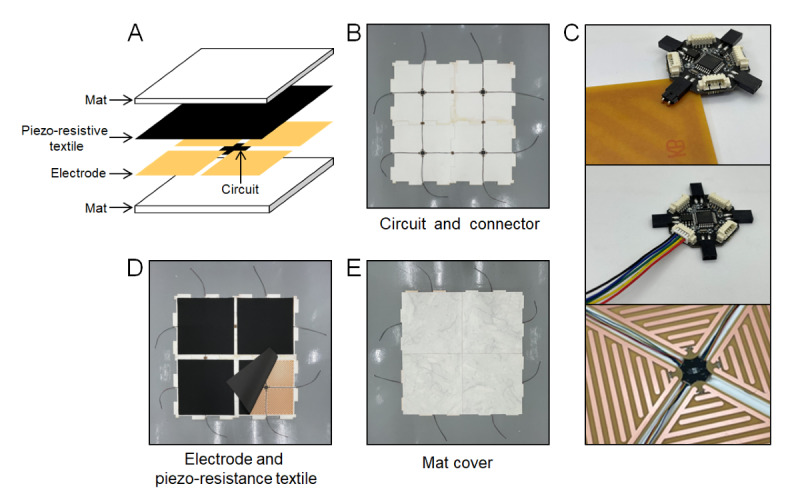
Figure 2.

Structure of the smart floor mat (SFM). (A) Schematic diagram of the SFM layer structure. Photographs of (B) bottom mats+MCU (microcontroller unit) circuits, (C) connection between MCU circuit and electrode plates and 5-pin connector, (D) piezo-resistive textiles on the bottom mat+MCU circuit and electrode plates, and (E) upper mats piezo-resistive textiles+bottom mat + MCU circuit and electrode plates.
