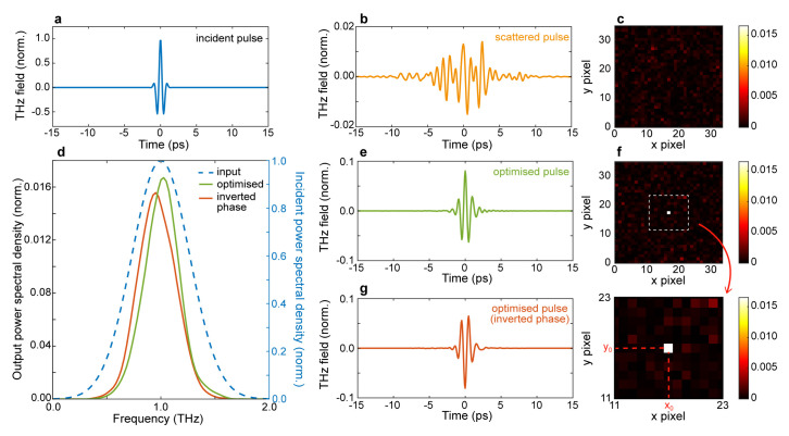
Figure 2. Spatiotemporal refocusing and pulse flip.
a. Input temporal profile. b. Temporal profile of a scattered pulse at the output of the scattering medium; the pulse is normalised with respect to the incident pulse. c. Non-optimised spatial intensity distribution at 1 THz. d. Power spectral density (PSD) spectrum of the optimal terahertz pulse (green line), optimised flipped pulse (orange line) and incident pulse (blue dashed line, right y-axis). e. Temporal profile of an optimised pulse. f. Optimised spatial intensity distribution at 1 THz. g. Temporal profile of an optimised pulse with an inverted (flipped) phase. Numerical parameters: spectral correlation Δ v c = 250 GHz, number of generations 10000, size of population per generation 100.

