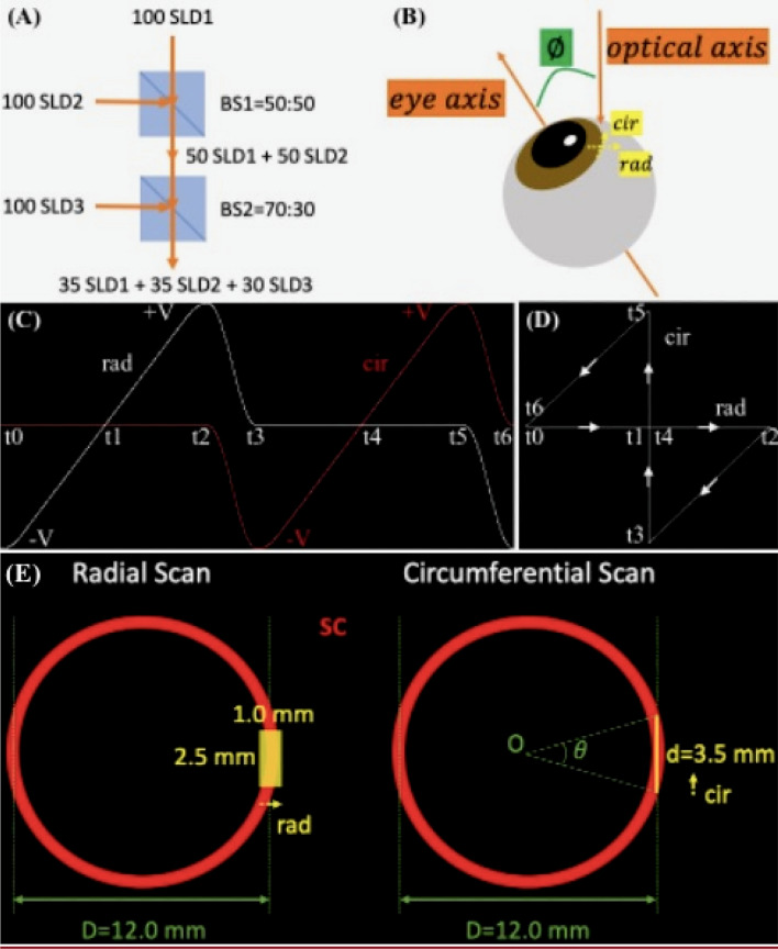
Figure 7.
SD-OCT imaging and experimental setup. To obtain a higher axial resolution, (A) three SLDs were combined by two beam splitters, BS1 and BS2, to have a broader optical source spectrum. Assuming that the three SLDs each have 100 arbitrary units of spectral powers, after BS1 and BS2 with the respective transmission-to-reflection ratios of 50:50 and 70:30, the optical source output is generated by the combined spectrum which is consisted of 3 comparable spectra from each SLD. (B) The human cadaver eye is positioned on a translational stage (not shown) and is tilted at an off-eye axis angle for best imaging of the iridocorneal angle features. (C) The timing diagram of the crossline scanning for one period of radial and circumferential scans. Strictly speaking, the ‘simultaneous’ radial and circumferential scans are in fact working alternately. The galvonometer voltage controlling the circumferential scan flattens at zero when it scans radially, vice versa. (D) shows the corresponding 2D trajectory of the OCT beam at different time points in (C). Note our crossline (radial and circumferential) scanning is part of the bowtie-shaped track, where the two hypotenuses’ paths are used to shift between the two scans. In the projection view along the eye axis, a continuous 2.5 mm translation of the eye shown in B (normal to the paper towards readers) resulted in (E) a radial scan and a 3.5-mm circumferential scan. The latter corresponds to a counter-clockwise, approximately of the full circumference of the angle structures, where D is the diameter of the ring-shaped SC estimated from reported averaged measurements of the spur-to-spur distance57. SLD: superluminescent diode; BS: beam splitter; rad: radial; cir: circumferential; SC: Schlemm’s canal.

