Figure 2.
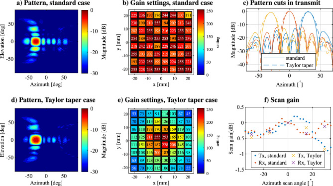
Measured radiation patterns in the standard case when scanning to in azimuth, normalized to the peak amplitude in (a), and the gain settings used to excite the array in (b). In (d) the pattern is shown when an additional Taylor taper is applied, and the respective gain settings are shown in (e). In (c) examples of the beam shapes are shown for the transmitter panel using the standard and Taylor taper case. In (f) the scanning gain is shown for all measured scanning angles, normalized to the center beam of each situation.

