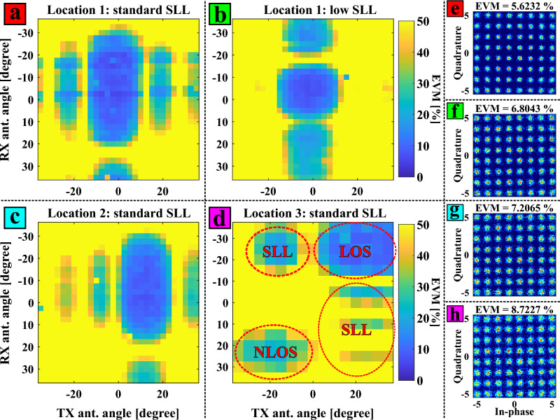
Figure 5.
Experimental 2D EVM map results obtained by realizing a double sweep in the transmitter and receiver azimuth beam angles for different end-user locations and system configurations: (a) location 1 with standard SLL configuration in the pPAA; (b) location 1 with low-SLL configuration; (c) location 2 with standard SLL; (d) location 3 with standard SLL illustrating LOS and NLOS transmission; (e)–(h) corresponding constellation diagrams of the minimum EVM points in the results from (a)–(d).

