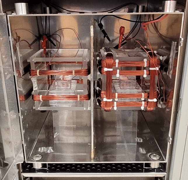
Figure 11.

Exposure Setup with Mu Metal Separation and Coil Configuration. On the left side, a square Helmholtz coil is used for the control group, while on the right side, a square Helmholtz coil is used for the treated group. The inner coils of both the control and treated coils are responsible for generating an SMF, while the outer coils generate an RF field. The magnetic fields generated by the coils are oriented perpendicular to the growth surface. A mu metal sheet is placed between the control and treated coils, ensuring separation, and minimizing magnetic field interference between the two groups.
