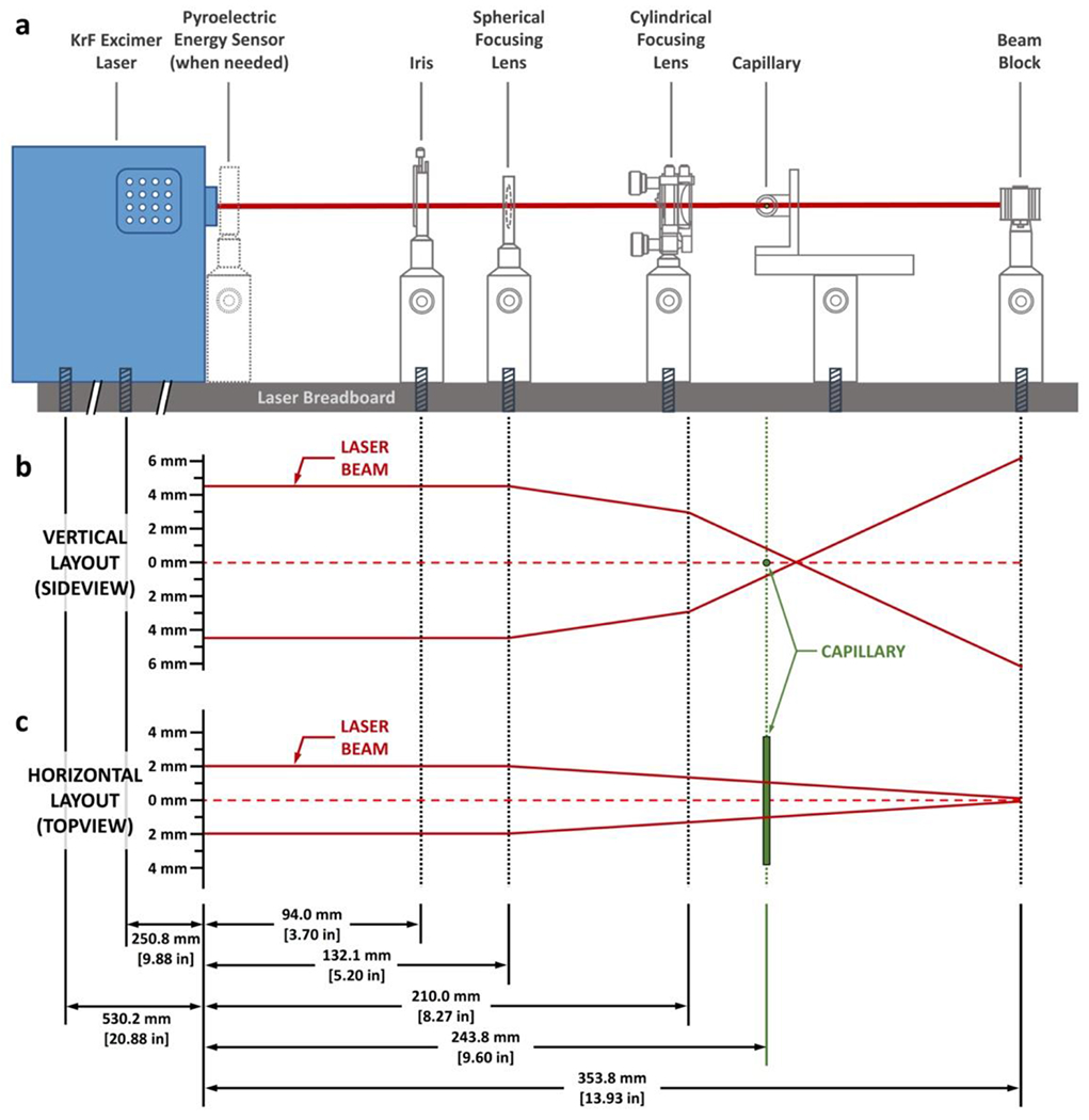
Fig. 2 |. Schematic illustration of the laser optics setup.

a, A sideview of the laser configuration. All laser optics are aligned in a linear fashion along the laser axis and are attached to the laser breadboard with screws. The positions of the laser optics, not their physical sizes, are drawn to scale. Detailed drawing of the optics setup and a blueprint of their alignment are available as Supplementary Fig. 2. b, Vertical layout of the laser beam and the effect of the laser optics on its pathway. The drawing is to scale, as indicated by the axis on the left. c, Horizontal layout of the laser beam and the effect of the laser optics on its pathway. Note that the cylindrical focusing lens has no effect on the laser beam on the horizontal direction as illustrated in this figure. The plot is drawn to scale as indicated by the axis on the left.
