
Figure 2.
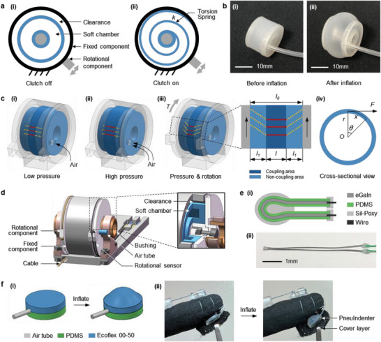
Mechanism and implementation of PneuClutch and PneuIndenter. a) Simplified cross‐sectional view of PneuClutch (i) before and (ii) after actuation. b) Images of soft chamber (i) before and (ii) after inflation. c) Illustrations of PneuClutch under (i) low pressure actuation, (ii) high pressure actuation, (iii) rotation after actuation and (iv) cross‐sectional view of (iii). Red lines and yellow dash lines indicates coupling and non‐coupling areas, respectively. d) PneuClutch implementation with an inset showing the inner structure. e) Rotational sensor (i) structure and (ii) image. f PneuIndenter (i) structure illustration and (ii) implementation beneath fingertip.