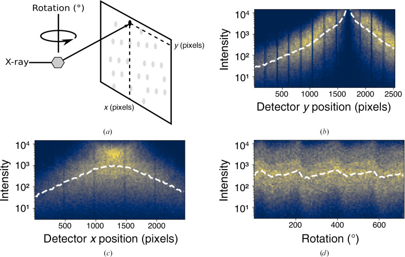
Figure 2.
(a) Schematic representation of a rotation experiment. The crystal sample (shown as a gray hexagon) diffracts the incident X-ray beam. Diffracted X-rays are measured on a detector (shown as gray spots) at a particular x, y detector coordinate. (b, c, d) Two-dimensional histograms showing the distribution of measured reflection intensities for a hen egg-white lysozyme data set. The dashed white lines show the median intensity in each metadata bin. (b, c) The observed reflection intensities are dependent on the detector position. (d) The observed reflection intensities vary as a function of crystal rotation.

