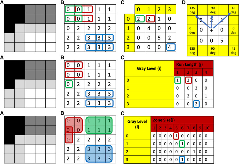
Figure 1.
Top row: (A) grayscale image with four different gray-levels. (B) Digitized version of the gray-level image with unique numerical values corresponding to the gray-level or a range of gray-levels (dependent on bin size of bin width) for each theoretical pixel/voxel. (C) GLCM map of the image obtained for distance 1 and direction 0 degrees. (D) This same process is then repeated in all other directions: i.e., 45, 90, and 135 deg, respectively. To obtain direction invariant results, all results are normalized and averaged. Middle row: (A) Grayscale image with four different gray-levels. (B) Digitized version of the gray-level image with unique numerical values corresponding to the gray-level or a range of gray-levels (dependent on bin size of bin width) for each theoretical pixel/voxel. (C) GLRLM map of the image obtained for direction zero degrees. This same process is then repeated in all other directions: i.e., 45, 90, and 135 deg, respectively. To obtain direction invariant results all results are normalized and averaged. Bottom row: (A) grayscale image with four different gray-levels. (B) Digitized version of the gray-level image with unique numerical values corresponding to the gray-level or a range of gray-levels (dependent on bin size of bin width) for each theoretical pixel/voxel. (C) GLSZM map of the image. GLCM, Gray-Level Co-Occurrence Matrix; GLRLM, Gray-Level Run-Length Matrix; GLSZM, Gray-Level Size-Zone Matrix.

