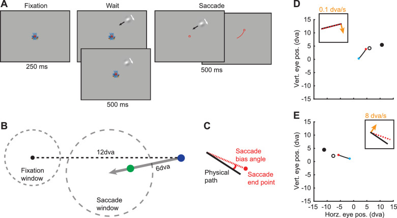
Figure 2.
Illustration of the DDST. (A) Marmosets were required to maintain fixation in the presence of the double-drift stimulus and then saccade to the stimulus. The stimulus was extinguished at the onset of the saccade. The top and bottom panels in the Wait period indicate the conditions with and without external motion. In the Fixation, Wait, and Saccade panels, the red circle indicates eye position. The Saccade panels illustrate that the stimulus remains on (left) up to 500 ms until a saccade is made (right). In the rightmost Saccade panel, the red line indicates eye trajectory and the red circle indicates postsaccadic eye position. (B) Diagram of the relative positions of the fixation point, stimulus path, and the fixation (2.25 dva radius) and saccade (3.5 dva radius) windows. The gray arrow indicates the stimulus path. The blue dot indicates the start position of the stimulus (nonzero external speed). The green dot indicates the position of the stimulus when the external speed is zero. (C) Illustration of saccade angle calculation. The saccade bias angle is the angle between the physical path and the saccade endpoint. Positive angles are in the direction of internal motion. (D, E) Example saccades from a marmoset to double-drift stimuli with very slow internal motion (D) and fast internal motion (E). Blue dots and red dots indicate the start and end of the saccades. The solid black and open black circles indicate the start position of the stimulus and the position of the stimulus at the time the saccade starts. The insets show a schematic of the physical path (black line), the direction of internal motion (orange arrow), and the angle of the saccade bias. (D) In this example (control condition), the internal motion is 0.1 dva/s, and there is almost no saccade error. (E) A large saccade bias angle is observed in this example with internal motion at 8 dva/s.

