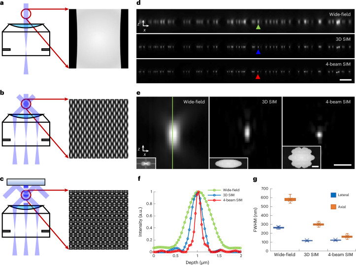
Fig. 1. Improving axial resolution in 3D SIM.
a–c, Schematic representations of beam illumination at objective back focal plane (BFP) and sample planes for wide-field microscopy (single-beam illumination, a), 3D SIM (three-beam illumination, b) and four-beam SIM (a mirror opposite the sample is used to back-reflect the central beam, producing four-beam interference, c). Higher magnification illumination views at right show fine axial structure in four-beam SIM pattern, absent in 3D SIM or wide-field microscopy. d, Axial cross-sectional views of 100-nm beads, as imaged in wide-field microscopy (top), 3D SIM (middle) and four-beam SIM (bottom). e, Higher magnification views of bead highlighted by colored arrowheads in d, illustrating progressive improvement in axial resolution. Insets show magnitude of OTFs (kx/kz plane) derived from images. f, Line profiles corresponding to bead images shown in e, taken along vertical green line in e. g, Quantification of lateral (blue) and axial (orange) FWHM for n = 102, 100 and 99 beads for wide-field microscopy, 3D SIM and four-beam SIM, respectively. See also Supplementary Table 1. Whiskers: maximum and minimum; center lines: medians; bounds of box: 75th and 25th percentiles; cross symbols: mean markers. Scale bars, 2 µm (d) and 500 nm (e); 1/200 nm−1 for Fourier transform insets in e. a.u., arbitrary units.

