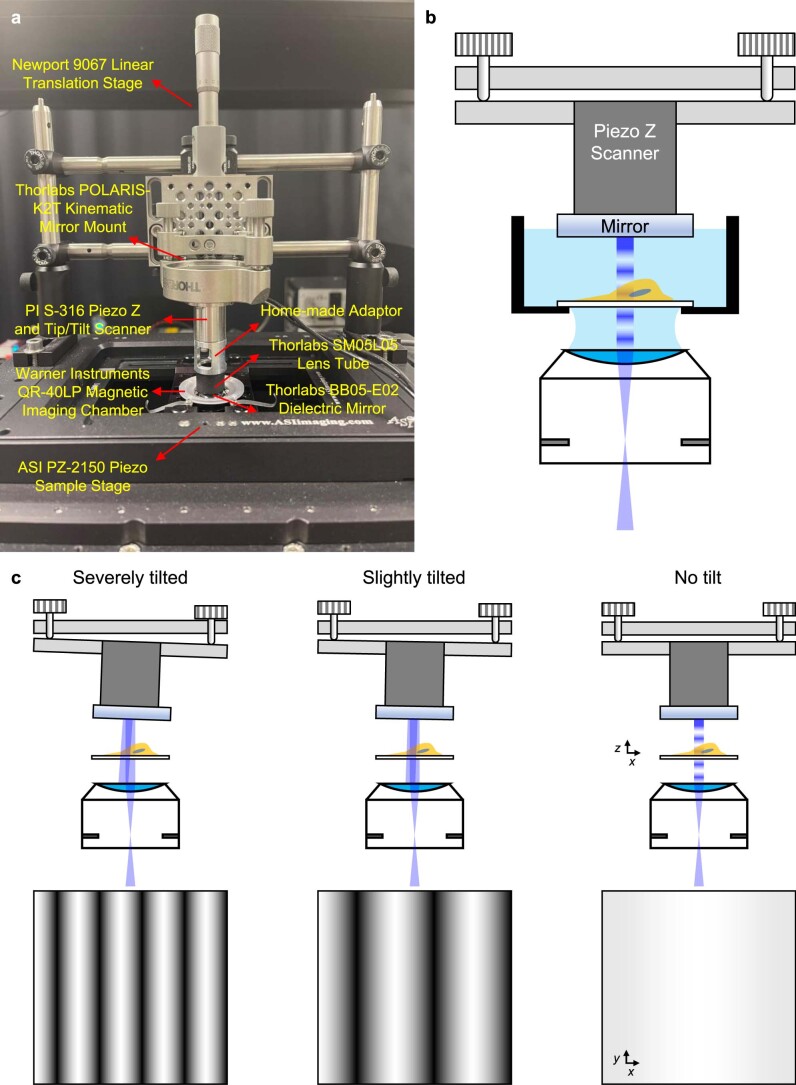
Extended Data Fig. 2. Mounting and aligning reflective mirror for four-beam SIM.
a) Photograph of mounting scheme, indicating hardware mounts with vendor information. PI: Physik Instrumente. b) Schematic to accompany a), showing kinematic mirror mount, Piezo Z scanner, mirror, sample, and objective lens. Schematic is not to scale. c) Alignment of the reflected beam is achieved by manually adjusting the knobs on the kinematic mirror mount until tilt is minimized. This can be achieved by monitoring the autofluorescence from a dirty coverslip immersed in liquid; tilt is minimized when a flat intensity profile is achieved when translating the sample through focus, yielding a purely axial modulation. Top images show reflected beam at different tilts of mirror; bottom images show corresponding planar images of autofluorescence when lateral modulation is present (left, middle) versus mostly axial modulation (right). See also Supplementary Video 1 and Methods for more information.

