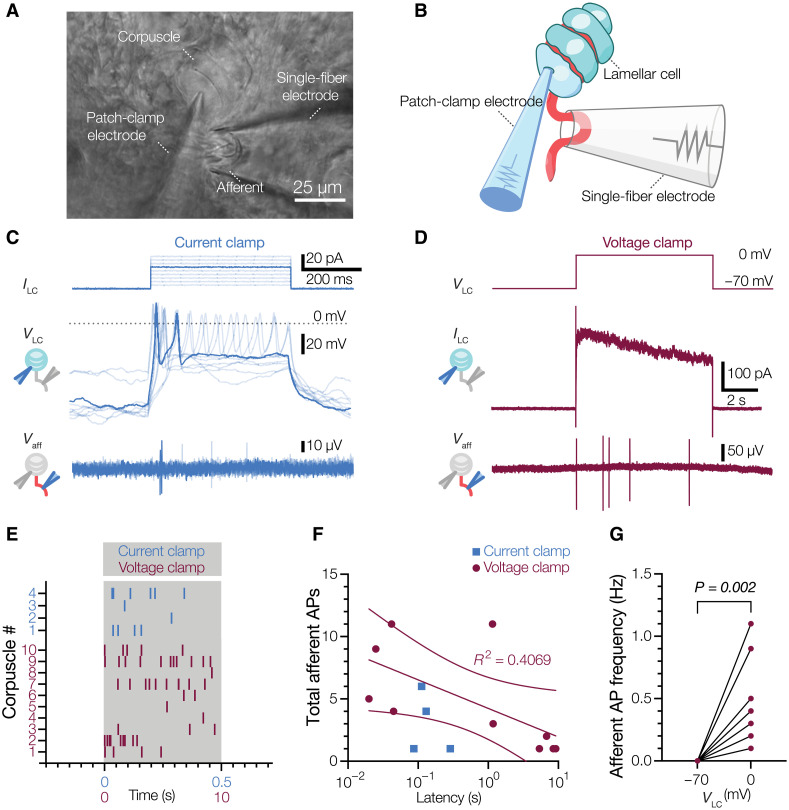
Fig. 4. Activation of a single LC is sufficient to drive afferent firing.
(A and B) Bright-field image (A) and schematic representation of the experimental setup (B) for simultaneous electrophysiological recordings from LC and afferent of a Meissner corpuscle in duck bill skin. (C) Current injection applied to the LC (ILC, top), voltage response and APs in the LC recorded with a potassium-based internal solution (VLC, middle), and extracellular voltage and APs in the afferent (Vaff, bottom). (D) Voltage step stimulus applied to the LC (VLC, top), current response with potassium-based internal solution in the LC (ILC, middle), and extracellular voltage and APs in the afferent (Vaff, bottom). (E) Raster plot of afferent AP firing for individual corpuscles during LC activation by either depolarizing current injections in the current clamp (blue) or voltage steps to 0 mV in the voltage clamp (maroon). Each vertical dash represents an individual AP. (F) Total number of afferent APs versus latency between onset of the stimulus and first AP. Dots represent data from individual corpuscles. The solid line is a fit to the liner equation and dashed lines are 95% confidence intervals of the linear fit. (G) Afferent AP frequency when LCs held at −70 and 0 mV. Lines connect data pairs from individual corpuscles. Wilcoxon matched pairs test.

