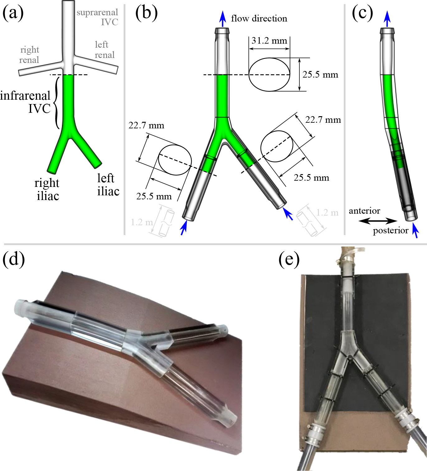
Figure 1:

(a) Original IVC model from [33] based on computed tomography measurements from ten patients. Only the iliac veins and infrarenal IVC (green) were included in the experimental model used herein. (b) Anterior view of the IVC model used in the particle image velocimetry (PIV) experiments. The IVC was scaled up to obtain an average hydraulic diameter of 28 mm in the infrarenal IVC. Upstream and downstream attachments were designed to transition from circular tubing to the elliptical cross-sectional shape of the vessels. (c) Sagittal view of the scaled IVC model. (d) Printed and polished physical model with foam support platform. (e) Assembled model connected to the mock flow loop.
