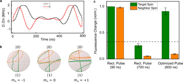
Figure 4.
(a) Optimized pulse shape for selectively applying a π-rotation
on spin i while leaving spin j unchanged,
where ωi – ωj = 1.1 MHz. The amplitudes of the in-phase,  (black), and out-of-phase,
  (red), components of the microwave signal
are shown as a function of time. (b) Calculated paths traced out on
the Bloch sphere by spin i (green) and spin j (orange) during application of the optimized pulse. The
hyperfine coupling to the nuclear spin has been included, and the
spin evolution is shown for each of the three nuclear spin states, mn. (c) Comparison of the cross-talk
caused by rectangular control pulses and the optimized control pulse.
The change in the spin-dependent fluorescence resulting from the application
of the respective pulses is shown for each spin, normalized to the
case of a rectangular pulse on resonance with that spin. The dashed
line indicates the maximum expected fluorescence change (1/3) if the spin is flipped for only one hyperfine case.
Error bars indicate the standard error of repeated measurements.

