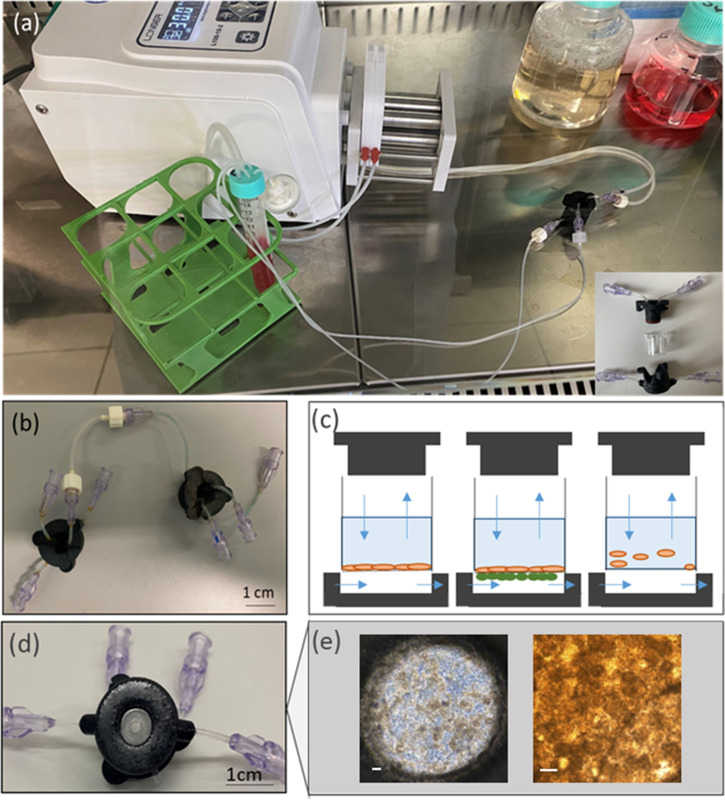
FIG. 1.
MINERVA device. (a) View of the MINERVA 2.0 setup. On the bottom right is an exploded representation of the MINERVA 2.0 assembly, consisting of apical and basal components enclosing the Transwell-like insert. (b) The Luer-lock connection guarantees the MINERVA possibility to be connected to other MINERVA devices. (c) Sketch of MINERVA 2.0 application. Single cell layer in adhesion in the insert (left), double cell layer across the insert membrane (center), cells in suspension in the insert (right). Blue arrows correspond to flow direction according to the design of the inlet and outlet. (d) Bottom view of MINERVA 2.0 with a transparent glass slide in the center for optical access. (e) The Caco-2 cell layer inside the device. The scale bar corresponds to 100 μm.

