FIG. 8.
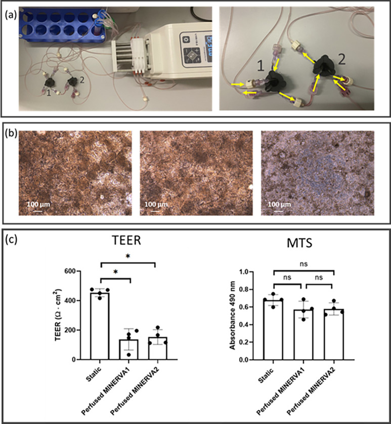
In-series perfusion via Luer-lock connection. (a) View of the MINERVA 2.0 setup for in-series perfusion (left) and magnification of the device connection (right). The inlet and the outlet of the apical chamber of the first device (labeled as 1 in the pictures) are connected to the pump and the reservoir, respectively. The inlet and the outlet of the basal chamber of the first device are connected to the pump and the inlet of the apical chamber of the second device (labeled as 2 in the pictures), respectively. The inlet and the outlet of the apical chamber of the second device are connected to the output of the first device's basal chamber and the reservoir, respectively. The inlet and the outlet of the basal chamber of the second device are connected to the pump and the reservoir, respectively. (b) Phase contrast images of Caco-2 cells cultured in perfused (left and center for first and second connected device, respectively) and in static (right) conditions. (c) TEER and MTS data for static and in-series perfusion. The experiment involved four replicates for each static and in-series perfused condition. *p < 0.05 Kruskal–Wallis test.

