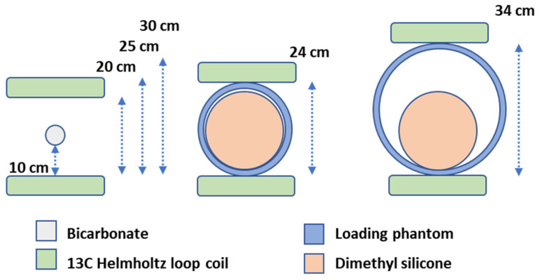
Figure A1.
Phantom and coil placements in carbon transmit gain examinations. Bicarbonate point phantom with no proton loading placed in the centre between the two Helmholtz loop coils (left). Loading setup using head (middle) and body (right) load rings with the head dimethyl silicone ball inside. Distances between the Helmholtz loop coil elements are noted in cm. Three distances were evaluated in the bicarbonate setup (20, 25, and 30 cm).

