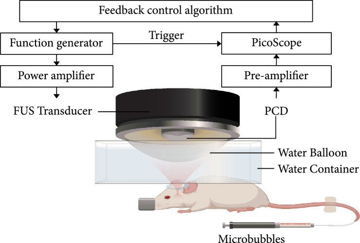
Figure 5.
Illustration of the feedback-controlled FUS system. The experiment setup was composed of three parts: (1) transmission: FUS transducer, function generator, and power amplifier; (2) receiving: PCD, preamplifier, and PicoScope; and (3) feedback control: a customized MATLAB program for the feedback control.

