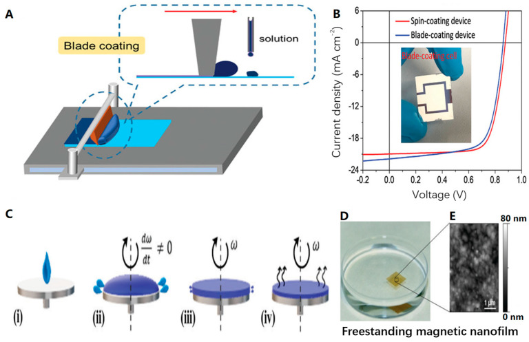
Figure 6.
(A) Schematic diagram of the scraping process. (B) J–V curves of a 1 cm2 blade coating device; the inset is the actual device [49]. Copyright 2019, John Wiley and Sons. (C) Schematic diagram of spin-coating process stages: (i) dispensing stage; (ii) substrate acceleration stage; (iii) steady liquid outflow; and (iv) solvent evaporation. (D) The prepared nanofilm floats on the water’s surface. (E) Atomic force microscope scan of the nanofilm [50]. Copyright 2021, Royal Society of Chemistry.

