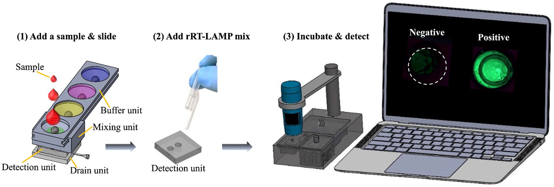
Fig. 2.

Process flow of using SPD and RAD for virus detection at POC. (1) A sample is loaded into the first reservoir of the buffer unit, followed by virus lysis, RNA binding, and washing steps by sliding the mixing unit along the buffer unit. All buffers pass through the paper in the detection unit due to the vacuum created by pulling out the plunger of a syringe connected to the drain unit. (2) The detection unit is separated from SPD, and the rRT-LAMP mix is added into the reaction wells. (3) The detection unit is placed in the seat of the heater chamber cap (Figure S1), followed by rRT-LAMP
