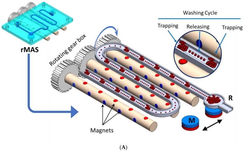
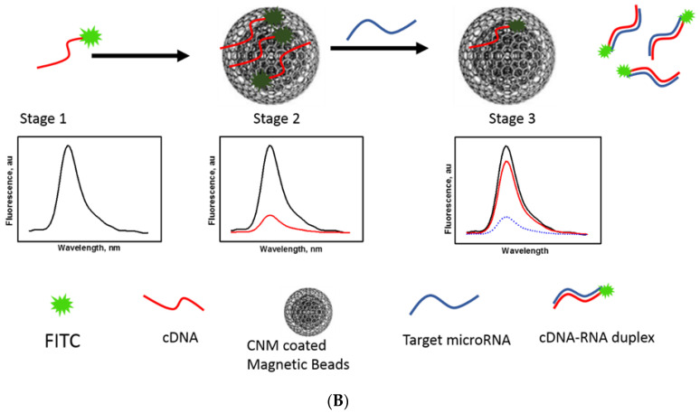
Figure 1.
(A) Schematic drawing of the magnetic separator showing the rotating magnetic system under the microfluidic chip in detail. A zoomed view of the beads “trapping and releasing” is shown in the inset. M is the permanent magnet used to trap the beads after purification and R is the collecting reservoir. (B) Schematic of the fluorescence switching mechanism in the CNM-coated magnetic nanobeads fluorescence assay for the detection of mir210. Stage 1: The FAM-labeled cDNA of mir210 has a high fluorescence signal. Stage 2: In the presence of CNM-coated magnetic beads, the fluorescence is quenched. Stage 3: Upon introducing mir210, the cDNA detached from the CNM surface and duplexed with mir210, which led to an increase in the fluorescence intensity.


