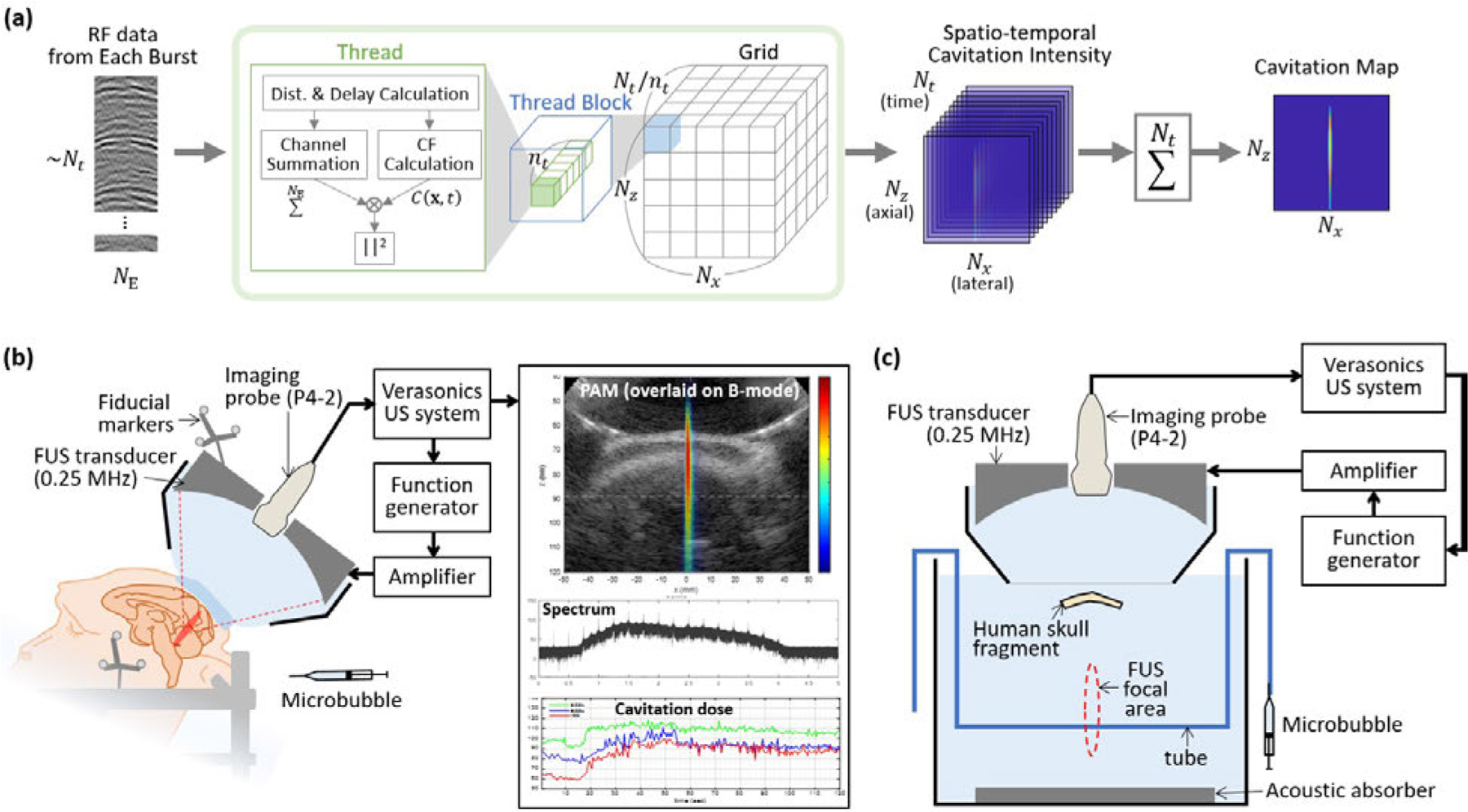
Fig. 1.

(a) Parallel processing scheme for reconstruction of a cavitation map from the RF channel data acquired in every FUS burst. In each thread block, threads were created where was the maximum number of threads per block. Dimensions of the grid were . In each CUDA thread, the intensity at a pixel and a time point was calculated, resulting a spatio-temporal cavitation intensity map with a size of . The final cavitation map for each burst was obtained by summing the results over time. (b) FUS system with cavitation monitoring for the in vivo NHP experiments. During the FUS treatment with the intravenous administration of microbubbles, the cavitation map, spectrum of the cavitation signal, and the cavitation dose were updated after each FUS burst at a rate of 2 Hz. Fiducial markers attached to the transducer and the stereotaxic frame were used for the neuronavigation-guidance targeting. (c) Experimental setup for the in vitro skull experiments. Therapeutic FUS pulses were transmitted from the FUS transducer and the microbubble inside the tube emitted the cavitation signals. The emitted signals were received by the imaging probe through the human skull.
