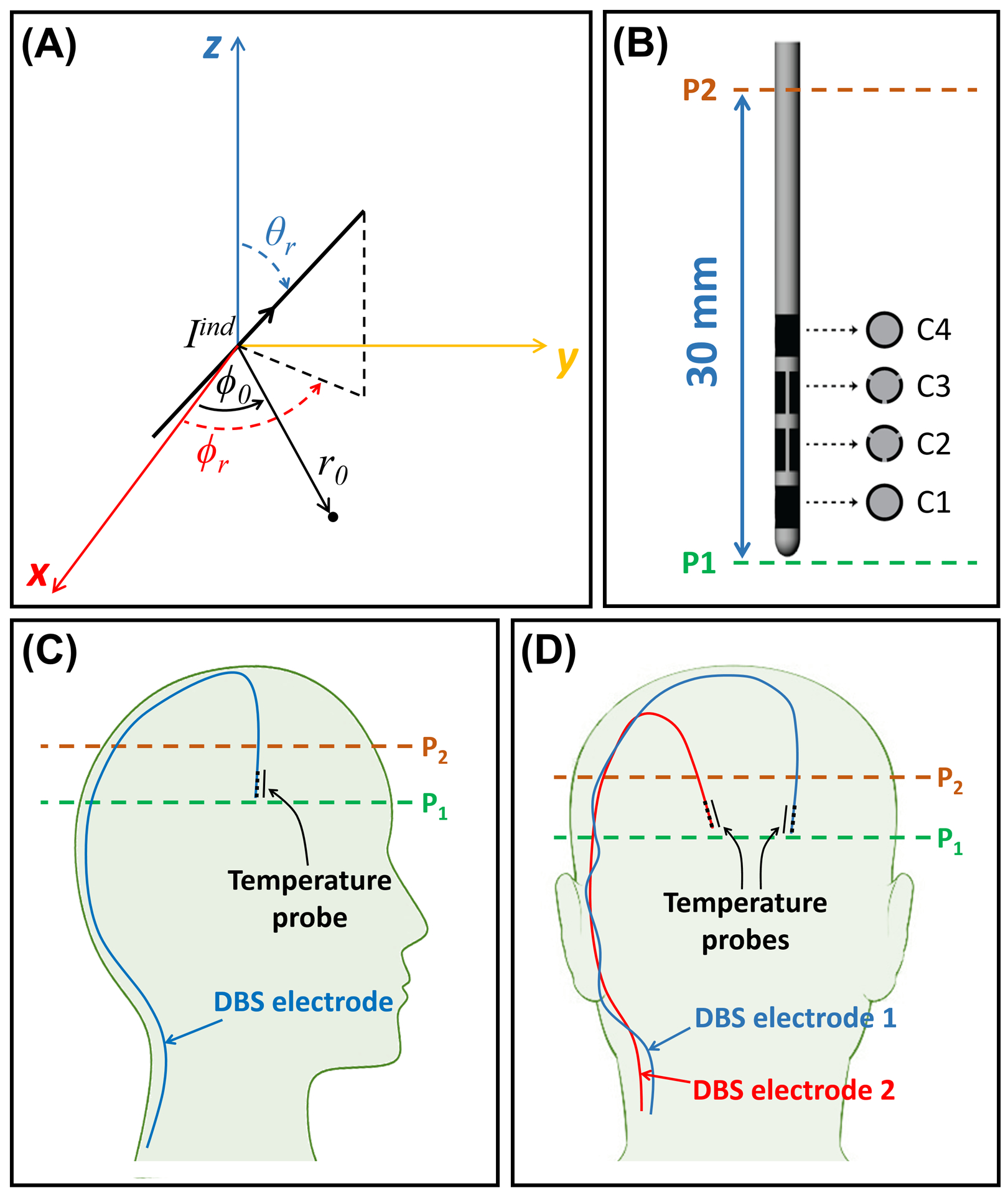
Figure 1.

Depiction of the DBS electrode and its orientation in the experimental setup. (A) The coordinate parameters used in calculations of the field of the induced current on an oblique DBS electrode. (B) Depiction of the commercial segmented DBS electrode used throughout this study. (C) A sagittal depiction of the DBS electrode’s trajectory in the unilateral configuration. (D) A coronal depiction of the DBS electrodes’ trajectories in the bilateral configuration. DBS, Deep Brain Stimulation
