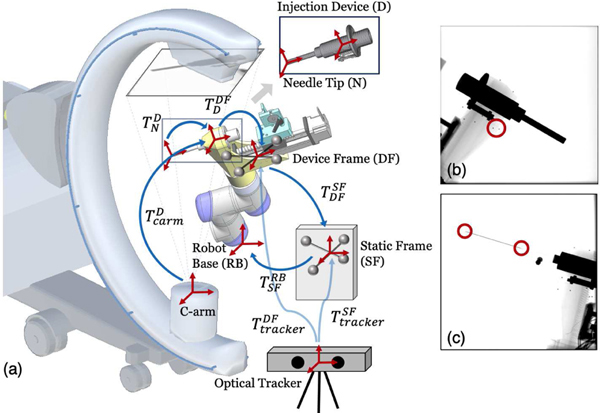
Fig. 3:
(a) System calibration scheme. Coordinate frames are marked as red cross arrows. Key transformations are shown in blue arrows. The 3D model of injection device for 2D/3D registration is illustrated on top. (b) An example X-ray image used for hand-eye calibration. Example BBs are marked in a red circle. (c) An example X-ray image used for needle calibration. The needle tip and base points are marked in red circles.

