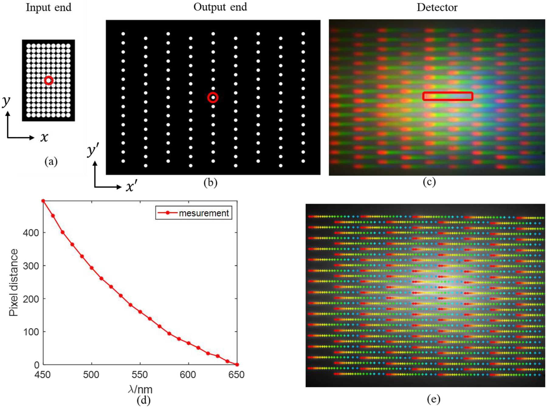
Figure 7.

Spatial and spectral calibration. (a) Layout of lightguides in the input end, (b) layout of the lightguides in the output end, (c) dispersed image captured with color CMOS sensor, (d) the pixel distance from reference band (640–650nm) to other wave bands from 450nm to 650nm, and (e) the pixel coordinates for 21 spectral bands for 15 × 9 lightguides, the color of marker varies according to the corresponding wavelength.
