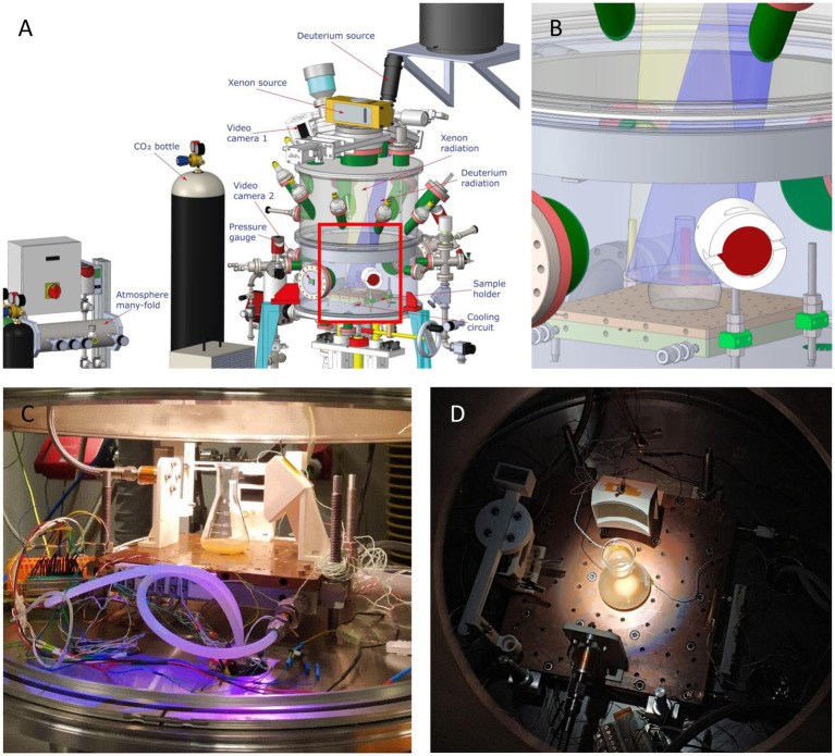
Figure 2.
Tolerance Assays in MARTE chamber. (A) Schematic drawing of the MARTE chamber, indicating the positions of the deuterium and xenon sources and the direction of the radiation they emit. The position of the equipment that maintains the CO2 atmosphere, the pressure gauge, the inlet and outlet of the cooling circuit and the sample holder are also showed. (B) Detail of the inset in Figure 2A representing the sample holder where the bacterial culture is placed. (C) Image of the culture of sample A in the MARTE chamber taken with the video camera 2. (D) Image of the culture of sample B in the MARTE chamber taken with the video camera 1.

