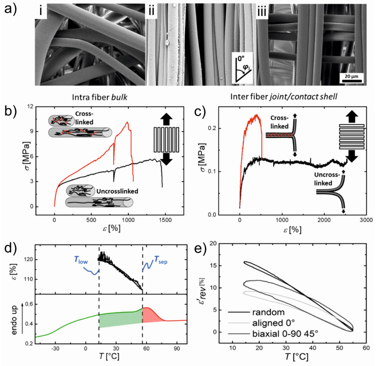
Figure 6.
(a) SEM images of PEVA fiber meshes after an electrospinning process at RT with different fiber arrangements: (i) random; (ii) aligned; and (iii) stacked 0–90°. (b,c) Mechanical properties of aligned fiber bundles at RT of the crosslinked (red curves) and uncrosslinked (black curves) fibers as well as a schematic description of the molecular processes at different strains. The red color utilized in the schemes denotes covalent crosslinks. (b) Loading along the fiber direction and (c) perpendicular to the fiber direction. (d) Actuator capability after implementation of a thermomechanical programming procedure. Upper: Reversible elongation and contraction by cooling and heating between Tlow and Thigh. Lower: DSC curve showing the broad thermal transition of the crosslinked electrospun fiber mesh scaffold. The curve is separated Tsep = 55 °C into green and red colors. Green: melting temperature range related to actuation units; Red: melting temperature range related to geometry-determining units. (e) Reversible actuation strain ε՜rev depending on different fiber alignments after the samples were programmed. The original data points were smoothed by adjacent averaging. Random: black curve; Biaxial (0–90°) (45°): gray curve; Aligned 0°: light gray curve. Reprinted with permission from [77].

