Fig. 5.
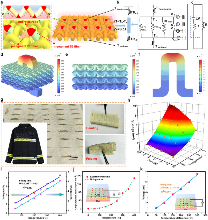
Electrical and thermal transport of p–n segmented TE fiber in TET. a Design structure of TET and p–n junction alternate between the hot and the cold sides. The illustration (left) is the TET’s cross section, confirming vertical arrangement of n-segment and p-segment in TE fibers. b Thermal diagram during heat transport in the prepared woven TET. Note: TR on behalf of thermal resistance (TRc1 and TRc2 are the thermal resistances of the cold and hot sides, respectively, and TRANFs, TR textile and TRTE are thermal resistance of the hollow ANFs/MMT fiber layer, textile substrate and p–n segmented TE fiber, respectively). Q represents the generated heat inputs (QP, h and QJ, h are input thermal produced via Peltier effect and Joule heating at the hot sides, respectively; QP, c and QJ, c are input thermal produced via Peltier effect and Joule heating at the cold sides, respectively). c Circuit diagram of TET during electrical transmission in TET. Note: R and r are external and internal resistances of TET, respectively. d The temperature distribution of the TET by finite element analysis. The temperature distribution of the aramid fabric substrate e and p–n segmented TE fiber f. g Optical image of the resultant TET through stitching the alternating p–n segmented TE fiber into a flexible aramid fabric (5 cm × 4.5 cm), exhibiting outstanding flexibility, including bending and folding. h Output voltage curve of TET at the different heating temperatures ranging from 100 to 400 °C. i Open-circuit voltage and current as functions of temperature. j Maximum power density of as-prepared TET at various temperatures. k Output voltage curve of TET concerning temperature difference

