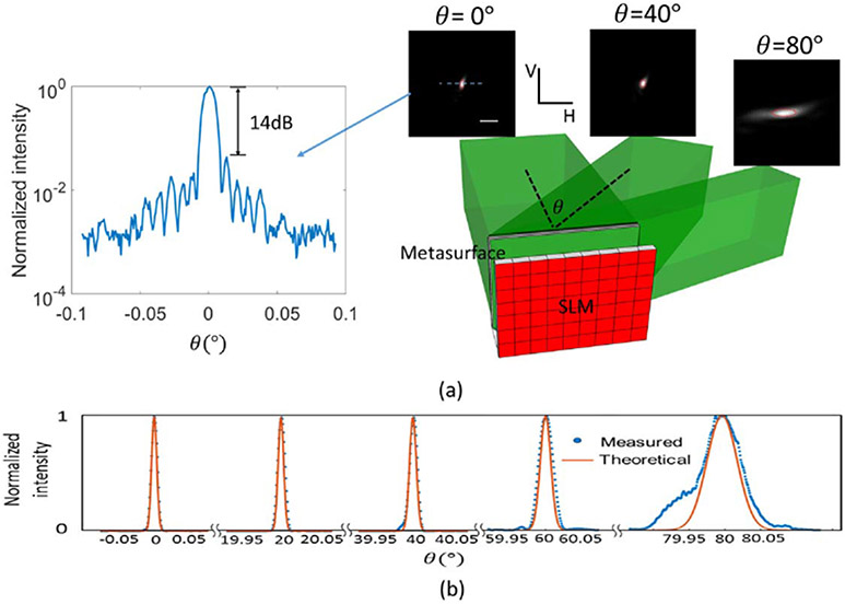
Fig. 4.
(a) Illustration of the steering scheme ( imaging system for imaging the SLM to the metasurface is not shown here). The far-field beam shapes at the steering angles of 0°, 40°, and 80° are shown. The red circles enclose the theoretical FWHM of the beams. The intensity line profile at normal direction is shown. (b) 1D far-field beam shapes at other steering angles. Red lines denote the theoretical shapes of the beams. Blue dots denote the measured data. Scale bar: 0.05° V, vertical axis; H, horizontal axis.

