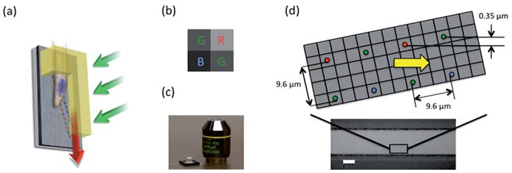
Fig. 1.

(a) The schematic plot of gravity driven color OFM. (b) The Bayer pattern for the color filter mask of the CMOS sensor. (c) The color OFM device comparing its size with a 10× microscope objective. (d) The schematic plot for the aperture array and the microscope image of an aligned PDMS channel on top of the aperture array. The scale bar is 20 microns.
