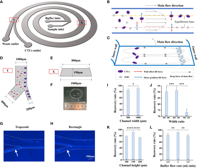
Figure 2.
Design and working principle of CTC detection platform. (A) Schematic of trapezoidal cross-section spiral channel with two inlets and two outlets. (B) Cells in the channel migrate under influence of wall effect lift force and shear gradient lift force. (C) Cells in the channel are also affected by drag force from dean flow and migrate to sized dependent equilibrium points of the cross section. (D) Size of bifurcation in the channel. (E) Size parameter of the trapezoidal cross-section of the channel. (F) Size and configuration of trapezoidal microfluidic chip. (G, H) Flow track of Hela cell in the trapezoid and rectangle microfluidic chips. (I) The recovery rate of 15 μm microbeads in different width of channel, n=15. (J) The recovery rate of 15 μm microbeads in different width ratios of CTC outlet to waste outlet, n=15. (K) The recovery rate of 15 μm microbeads in different channel heights, n=15. (L) The recovery rate of 15 μm microbeads in different buffer flow rates, n=15. Data are presented as the mean ± SD, NS: not significant; *p < 0.05, **p < 0.01, ***p < 0.001, ****p < 0.0001 by one-way ANOVA test or two-tailed Student t-test, error bars indicate s.e.m.

