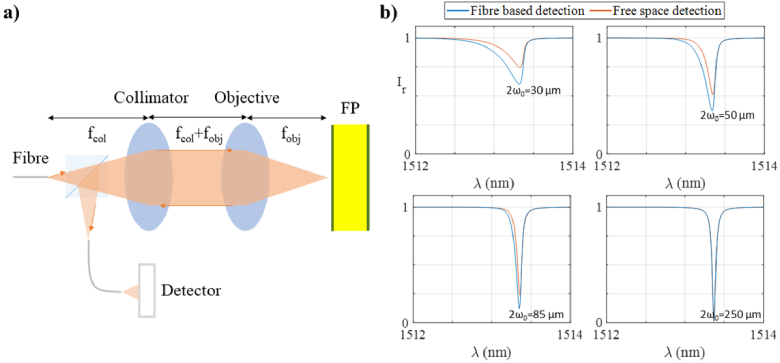
Fig. 5.
a) Schematic diagram of the modelled optical system consisting of an optical fibre (MFD = 10.4 µm) illuminating an FP etalon (h = 102 µm, n = 1.444, R1 = R2 = 97%) using a collimator and an objective in a 4f configuration where the reflected beam is directed on to a fibre-coupled detector; and b) Comparison of ITFs in reflection mode for fibre based detection and free space detection (blue and red, respectively), for different spot sizes.

