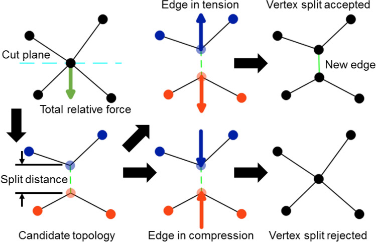
Figure 3.
Diagram of a possible vertex split operation on a candidate vertex. The total relative force (green arrow) on connected vertices is calculated with respect to the force acting on a candidate vertex (top left). A candidate topology is calculated from a cut plane that intersects the candidate vertex with a normal along the total relative force, which places two vertices of the split operation on opposite sides of the cut plane and separated by a small distance (i.e., the “split distance”, bottom left). The vertex split operation is accepted when the newly created edge of the vertex split operation (green dashed line) is predicted to be in tension (top right) and rejected when in compression (bottom right). Circles and lines indicate vertices and edges, respectively. Blue and orange vertices indicate the vertices that define two different surfaces in the candidate topology. Blue and orange arrows indicate the total relative force on each vertex of the split operation in the candidate topology.

