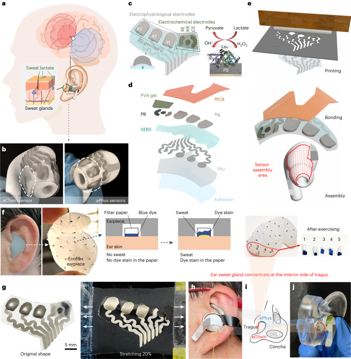
Fig. 1. Design of the in-ear integrated sensors.
a, Design schematic of the in-ear integrated sensors. The grey and green dashed outlines denote the electrophysiological and electrochemical sensor sites registering brain activity and sweat secretion, respectively. b, Assembled in-ear integrated electrophysiological (ePhys) and electrochemical (eChem) sensing electrodes. The white dashed outlines denote the locations of the electrophysiological and electrochemical electrodes. c, Layout of the in-ear integrated sensors (left) showing 3D cushioning of the electrophysiological electrodes and indicating the mechanism of sweat lactate electrochemical sensing. LOx on the working electrode surface (right) catalyses oxidation of lactate acid into pyruvate and hydrogen peroxide (H2O2). In turn, PB transforms H2O2 into hydroxyl ions (OH−), generating a sensing current proportional to lactate concentration. d, Layer-by-layer structure. From bottom to top, the sensors were made of adhesive, TPU, SEBS, PB, stretchable Ag, PVA hydrogel and flexible printed circuit board (fPCB). e, Fabrication process of the sensors showing three main procedural steps: printing of sensors, bonding with electronics and assembly to earphones (details can be found in Extended Data Fig. 2). f, In-ear sweat mapping for electrochemical sensing using an Ecoflex earpiece with distributed filter papers, the distribution of which was used as sweat secretion indicators. g, Integrated sensors before assembly and after 20% latitudinal stretching. h, Assembled integrated sensors in the ear. The grey dashed outlines indicate the locations of electrophysiological REF and DRL electrodes. i, Geometry of the ePhys, REF, DRL and eChem electrodes. j, Skin contact locations of the ePhys and eChem sensors as revealed by insertion in an ear phantom.

