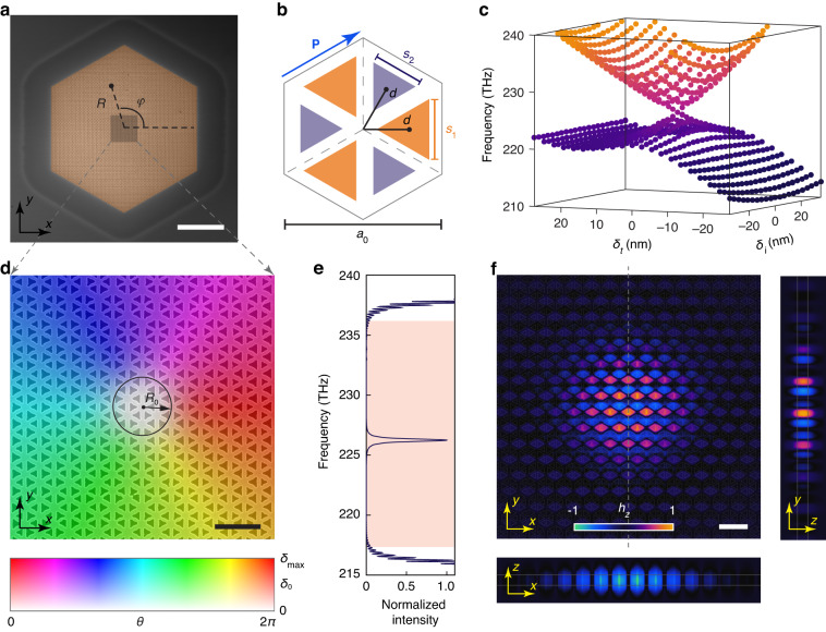
Fig. 2. Design and fabrication of the Dirac-vortex laser cavity.
a Scanning electron microscope image of the fabricated Dirac-vortex topological photonic crystal laser. R and φ are respectively the radial and angular coordinates of the real space. Scale bar, 10 µm. b Illustration of the detailed structure in a unit cell. The lattice constant of the hexagonal photonic crystal is a0 = 641 nm. Each unit cell contains six triangular holes that can be classified into two groups (colored in purple and orange). The side lengths of the two groups of triangular holes are governed by parameters (s1, s2) = (, ) with s0 = 220 nm. The relative distance from the centers of these triangular holes to the center of the unit cell is d = a0/3 − δt. Here, breaks the C2 inversion symmetry and δt breaks the TP translational symmetry along the vector P (marked by the blue arrow). c Simulated eigenfrequencies of the bulk states at the Γ point of the first Brillouin zone with different values of δi and δt. d Scanning electron microscope image of the photonic crystal structure near the vortex center. It is color-coded by the spatially varying parameters δ0(R) = δmax·[tanh(R/R0)]4 and θ(φ) = φ, where R0 defines the size of the region with a near-zero value of δ0(R). Scale bar, 1 µm. e Simulated normalized intensity spectrum of the Dirac-vortex cavity. A topological Majorana bound state exists in the bulk bandgap (pink region). f Simulated modal profiles (hz component) of the Majorana bound state. Scale bar, 1 µm

